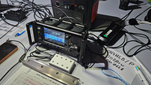
If you want a compact and sturdy enclosure for your IC-705 keypad, here’s a simple and low-cost way to put it together. The whole project can be built with basic tools and a bit of patience.


BOM
- 1 x Stereo Sockets PJ-324
- 8 x 12x12x15mm Tactile switch
- 8 x 0603 (1608) SMD 10nf Capacitors
- Resistors 1206 (3126) (although you need to buy them per 100)
- 4 x 1.5K Ohm resistor
- 2 x 2.2K Ohm resistor
- 2 x 4.7K Ohm resistor
- 1 x 3.5 mm aux cable
- 1 x Case 80x50x20mm
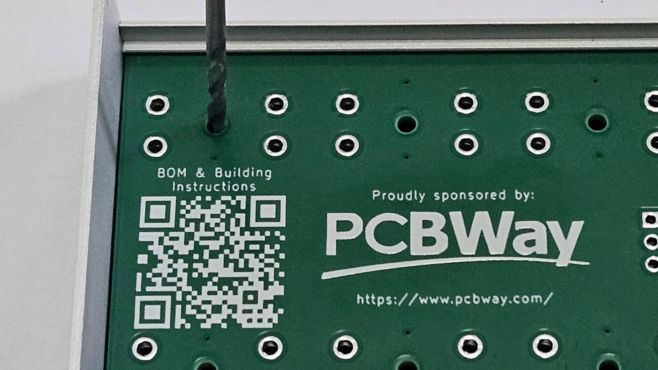
Get your PCB
I still have a few PCBs in stock. If you cover the postage, I can send one your way. Depending on your location, it may also be more cost-effective to order directly from PCBWay. Feel free to reach out and we can see what works best for you.

Building Instructions
Step 1: The enclosure
We use a standard aluminium project box (80 × 50 × 20 mm) as the housing. These enclosures are easy to find and provide excellent protection.
The custom PCB is designed to slide perfectly into the internal rails of the box, making installation straightforward and secure.
Step 2: Choosing the buttons
The keypad uses 12 × 12 mm push buttons with plungers.
If you use 15 mm plungers, the button tops will sit just above the surface of the enclosure.
For a more pronounced feel, choose 16 mm or 17 mm plungers instead.
Step 3: Drilling the holes
The PCB footprints of the buttons have 2 mm guide holes to make drilling easier.
Here’s how to proceed:
- Place the PCB in the top half of the enclosure and fasten the side screws—this holds it firmly in place.
- Using a 2 mm drill bit, make pilot holes through the enclosure.
- Remove the PCB and enlarge the holes gradually to the final size:
3 mm → 4 mm → 5 mm → 5.5 mm → 6 mm → 6.5 mm. - Once all holes are drilled, check that the push buttons fit snugly
Step 4: Soldering the components
You can solder the SMD components with a fine-tipped soldering iron, or – if you prefer – a bit of solder paste and a hot air gun works just as well.
The push buttons and the 3.5 mm connector are through‑hole parts and should be soldered last.
Step 5: Finishing touches
Drill an opening on the side of the enclosure for the 3.5 mm connector.
After fitting it, assemble the rest of the box—and your external keypad for the IC-705 is ready to plug in and use.