The original design features the Radio-Shack P/N 270-233 box, wich measures 5″ 1/16 x 2″ 5/8 x 1″ 5/8. I found a box with similar measurements from Velleman, the WCAH2853 PO#1238636. This box measures 130 mm x 70 mm x 45 mm. The biggest difference between these two boxes is that the lid from the Velleman box is also from plastic and not from aluminium. My supplier did also had a box with an aluminium lid, but it had a ugly blue color and the material felt more brittle. I’ll let you know if it’s a big deal to have an aluminium lid or not.

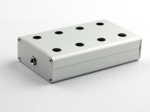
Drilling some holes
I did not have exact dimentions to work with, so I eyeballed it a bit. Trying to get the holes nicely lined up whilst ensuring there is suffisient room in the box between the parts to place resistors and toroids.
First row from the left: a 10 mm hole for the first BNC connector. 15 mm from the top, 28 mm from the left. The second 10 mm hole for the other BNC connector is placed 15 mm from the top and 64 mm from the left. The two holes on the left are for the banana jack sockets. If you are planning to use a banana jack adapter that connects two banana jacks, be sure to measure the exact space between these two hole. I don’t have such connector and don’t plan to use it, so I just drilled them 15 mm apart. 12 mm from the top and respectively 35 mm and 20 mm from the right.
Second row on the left at 20 mm from the left and 30 mm from the top is a 3 mm hole for the 3 mm led light. The led will fit in here snugly and only needs to be secured with hotglue to be sure it will not fall out. Mine sticks so tight, I don’t even think it’s needed to hotglue it. Second row on the right, below the hole for the black banana jack socket is a 6 mm hole for the SW-2, SPST On-On switch. I’ve located it at 15 mm from the right and 24 mm from the top.
On the bottom row we will drill two 6 mm holes for SW-3, a DPDT On-On switch and SW-1, a DPDT On-Off-On switch. Respectivly 15 mm and 38 mm from the left and 20 mm from the bottom (I placed them to close to eachother (17 mm and 35 mm), so there is no room anymore for the FT37-43 toroid. Don’t make the same mistake 😉 ). The holes for the capacitor are the trickiest ones. These need to be aligned very well so the capacitor can be scewed to the lid. The big holes are 8 mm wide and the small holes 2,5 mm. I’ve placed the center of the left big hole right under the 2nd BNC connector at 64 mm from the left and at the same hight (20 mm) as the switches from the bottom. According to the datasheet of the CMB-443BF the small holes are 14,8 mm apart from eachother. So, 7,4 mm apart from the center. Start drilling with your smalles dril, you can always move up a little to the left or the right using your bigger drill if you are a little out of the direction.
Installing the components
Now all the holes are drilled, it’s just a matter of putting the components in the right place. Make sure they are aligned properly and that all nuts and screws are tightened securely.