Using the original schematic as a starting point, I reworked the electrical diagram and incorporated an A4988/DRV8825 module.
You can download a pdf file of the reworked schematic here: MagLoopTuner.pdf
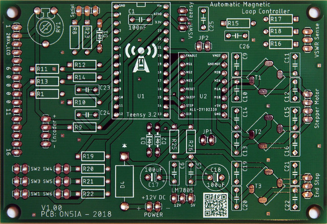
The two jumpers in the schematic deserve a little explanation:
JP1 connects the sleep and reset pins of the A4988/DRV8825 module board. I’ve seen schematics where these pins are soldered together, but I preferred to use a jumper. This way you have the possibility to add a reset switch, or if you think it’s not needed, just bridge the two contacts.
JP2 was incorporated for future use. It connects the unused pin 19 of the Teensy 3.2 with pin MS3 of the A4988/DRV8825 module. Without this connection, the maximum resolution of the magnetic loop controller is a 1/8th step. With some extra coding, we could drive the stepper motor as precise as 1/16th step (with the A4988) or even 1/32th step (with the DRV8825). This coding is not yet done, and I’m also not sure if this fine stepping is useful for this project, but I thought it was a nice idea to experiment with it. So for now, you can leave JP2 open.
If you are not using end-stop switches, then there is no need for D2, D3, R25, R26, C19, C20, C21, C22 and T3.
Depending on the type or brand of the rotary encoder, the A or B phase can be reversed. However, VCC and G must always be respected. You can check the correct wiring of A and B when you scroll through the menu. Turning the rotary encoder clockwise must increase the menu option, the steps and the frequency. When this is correctly done, you can start checking the wiring of the stepper motor. In order for the backlash and auto-tune function to work correctly, the capacity must go down when you turn the rotary encoder clockwise.
Don’t need the SWR / power meter function? Then you don’t need R15, R16, R17, R18, C25, C26 and R20, R21 and R22 (and their corresponding switches) either.
Please check Loftur’s project page for a more detailed explanation, the BOM and building instructions: https://sites.google.com/site/lofturj/to-automatically-tune-a-magnetic-loop-antenna
For any inquiries or questions about the PCB, please send an email to on5ia@uba.be. Add my email address in your contacts to prevent my response email from landing in your spam folder.

Hi
Have ordered one of lofturs boards but come up against a wall obtaining the A4975 drivers apparently the dip version is now end of life so after spending out on all the components I was looking at having to order some suspect ics from china but now I have discovered a board that runs on the same pololu / Stepsticks as my 3d printers yayyy. Please could you send details of the board and also advise as to whether or not the rest of the components that I have sourced and ordered are the same Thank you
73’s M6OYY
Hi Neil,
The fact that is was way easier to find good working A4988 or DVR8825 modules instead of the A4975 ic was the main reason why I designed my own PCB. In the past I’ve ordered a couple of boards from Loftur and followed the route to AliExpress, where I had to buy the IC’s in bulk. The results were various. Some IC’s were the real deal, some of them were knockoffs that seemed to work and others were just plain counterfeit and defective.
All other components on my PCB have the same value and name as on Loftur’s PCB and BOM. All components you already bought can be (re)used. Except maybe the common mode chokes. I’m using CMS1-8-R on my PCB. These are available at DigiKey and Mouser, but you can also find equivalents on eBay.
I’ll send you the details of the board by mail.
73 de ON5IA
What is the cost of complete kit in USD.
THNX KK7NJ
Hello,
I don’t have complete kits for sale. But I can give you some information on the cost.
The link below is a link to a Mouser shopping basket, with all needed components (less components are needed if you use the A4988 PCB board). Total amount of this basket is around $117.
https://www.mouser.be/ProjectManager/ProjectDetail.aspx?AccessID=9512640e59
To this add the price of the PCB and SWR Bridge kit, the screen bezel from DHmicro.com ($3,5 + shipping) and a LCD screen from AliExpress (+- $3) and you will end up around $160 for all needed components for this tuner.
Savings can be made if you order some components on AliExpress, but you’ll have to wait much longer. Another possibility is to find other hams in your area that also would like to build this tuner. Electronic components tend to become a lot cheaper if you buy them in bulk.
73 de ON5IA