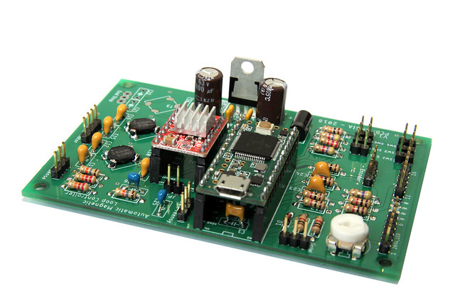
I took some time to solder another PCB for an Automatic Magnetic Loop Tuner. I made some pictures of the final result which I would like to share with you.
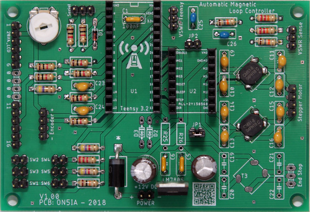
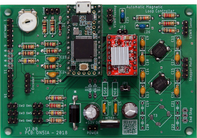
This is a view from the top of a populated PCB. The Teensy 3.2 and the A4988 stepper module are not yet installed. This loop controller won’t need the end stop feature. Therefor D2, D3, R25, R26, C19, C20, C21, C22, T3 and the 3 pin header for the end stop connector, are not installed.
C1 is located underneath the Teensy 3.2. This capacitor can be soldered upright. There is plenty of space, so no need to lay it flat on the board.
Here we have both the Teensy 3.2 and the A4988 stepper module installed. Note that a jumper is placed over JP1, but that JP2 is left open. JP1 connects “Sleep” and “Reset”. JP2 is for future use. When using a DRV8825 stepper module it gives us the possibility to connect the unused Teensy 3.2 pin 19 with pin MS3 of the DRV8825. With some additional programming to the software, this could enable the 1/32 step stepper resolution. This however has not yet been programmer, nor tested.
If there is one thing I would change to this board it’s the re-positioning of the LM7805 voltage regulator. The ground plane in facing inward which makes it difficult to attach a heat-sink. This can be solved easily by bending the legs of the LM7805 so the ground will face upwards, or by connecting it from the underside of the PCB and connecting the ground to the metal enclosure the whole PCB will be put in.
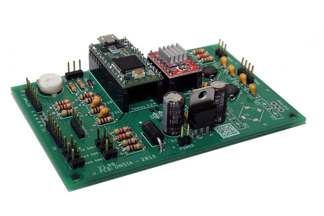
On this last picture, you can see capacitor C1 has plenty of space and is enjoying the company and security of the Teensy 3.2 😉