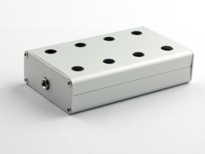
The PCB is soldered, we did the metal work and the paint job on the project box. Now we are going to assemble it further and finish the Automatic Magnetic Loop Tuner. The only thing we need to do before we put the switches, screen and connectors in the project box and connect them to the PCB, is to solder the connection wires.
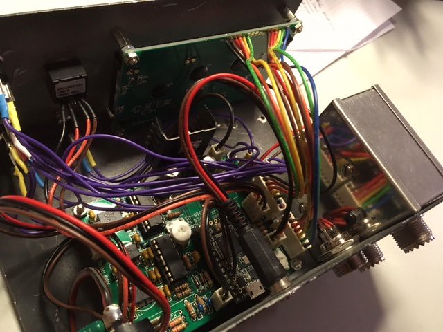
For these wires, I used Dupont wires, with female connectors of 2, 3, 4 or two times 6 pins. The one with two times 6 pins does not really exist, you have to make it yourself. For this, I took a rainbow colour multi cable Dupont wire. Removed the single female connectors and replaced them with 6 pin Dupont connectors.
![10sets-70cm-4-Pin-Female-to-Female-Jumper-Wire-Dupont-Cable-for-3d-Printer-Endstops-Main[1]](https://farm1.staticflickr.com/806/40786774562_528fd81da7.jpg)
![30cm-40pcs-in-Row-Dupont-Cable-30cm-2-54mm-1pin-1p-1p-Female-to-Female.jpg_640x640[1]](https://farm1.staticflickr.com/818/39933902555_3c2b4bcf76_z.jpg)
Use some shrink tube to make sure all connections are well insulated and will not cause a short circuit.
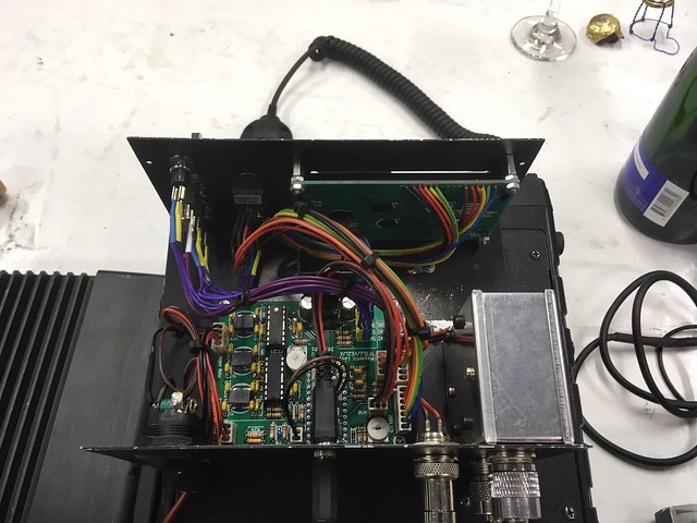
When done, it’s only a matter of connecting the right switch to the right header on the PCB. Check the electrical diagram to know the function of each switch.
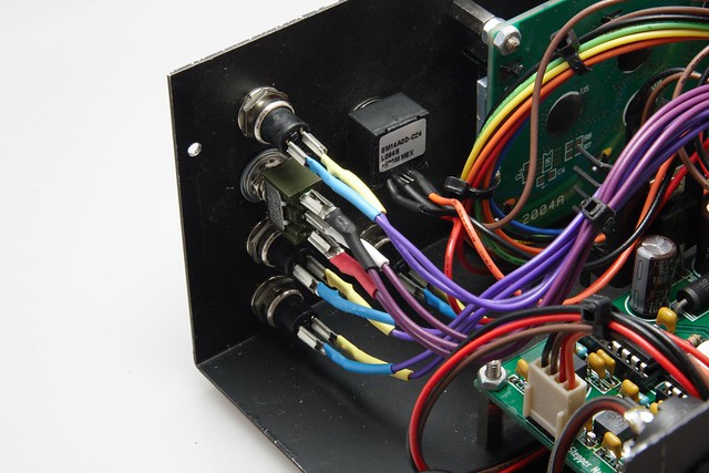
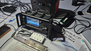
When everything is connected, you might want to tie together some wires to tidy things up. Your project will certainly look better and not like a rats nest of wires. Put the lid on the box, fasten the screws and your Automatic Magnetic Loop Tuner is ready to be used.