Introduction
Note 2020-12-12: I’m making a PCB for an IC-7300 keyboard. Check the blogpost and check in regularly to follow the progress.
Endlessly calling CQ during a contest or special call activation can give you a sore throat. Voice keyers were invented for this particular matter. A voice keyer is even built-in in the IC-7300, so at first, there is no need for an external device.
This voice keyer has 8 presets and can be used as a keyer for voice, CW or RTTY. The only drawback is that this keyer is only accessible when the voice keyer option is visible on the display. And at that time you can’t see any other screen that might be more of an interest to you than the voice keyer buttons such as a larger scope, the audio input and output and your meters (SWR, ALC, COMP and I). An external keyboard would be of great help.
Strange enough this external keyboard is not provided by Icom, you are forced to buy an aftermarket device, or… build it yourself. The schematics for this are made available by Icom in their manual on page 12-2.
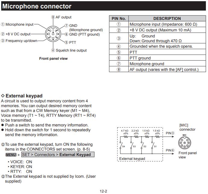
A prerequisite for me was that I could still use the original mic when the keyboard was attached and that when I don’t use the original mic, I still have the same capabilities as if I’m using the original mic. So both schematics need to be combined.
Gather the needed components
Enclosure
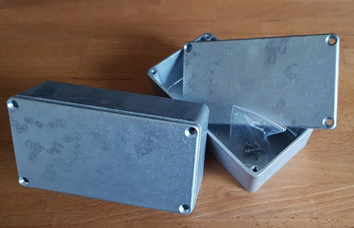
Except for the resistors all I needed was bought on AliExpress. For the enclosure, I choose for an aluminium box measuring 122(W) x 66.5(H) x 39.5(L)mm. Guitar enthusiasts use these enclosures to make so-called stomp boxes or effects units. Manufacturer Hammond brought an enclosure with these dimension to the market as model 125B/1590N1. On Aliexpress you can find one here.
Buttons
You can choose whatever momentary switch you like for this project. I went for black plastic 12 mm momentary push-buttons.
Microphone connectors
Icom uses an 8-pin microphone connector. These GX16 connectors, sometimes also referred to as circular aviation socket plug, can be found in abundance on AliExpress. Search for GX16 8 male female because we want two male sockets and 2 female sockets. The male sockets are to be placed on the enclosure, the female sockets are needed to build the cable to connect the external keyboard to the radio.
Cable
Finding a suitable cable that has sufficient inner strands, is not to thick and looks good was not so easy. Mini Din 8 pin extension cables can be found easily, but they do often come in an ugly beige colour. As we only need 6 inner strands, I figured out a Mini Din 6 pin cable would do the trick as well. I still had 1 meter of this cable in my stock as I once used it to build a data interface for my trusty Yaesu FT857-D.
Resistors
We need one 470 Ohm, one 4,7k Ohm, one 2,2k Ohm and two 1,5k Ohm resistors. All 5% and 1/4 Watt.
Audio Jack Sockets
When looking for audio jack sockets, look for those with a screw on the inside of the enclosure. Not only do they look better, but I also have the impression the quality is a bit better.
Preparing the enclosure

On the top of the box 7 holes needed to be drilled. 4 on the top row, 3 on the bottom row. Each hole has to be 12mm.
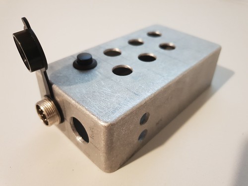
On the left two 20mm holes are drilled for the GX16 connectors and on the front 2 7mm holes were made for the 3.5mm stereo jacks.
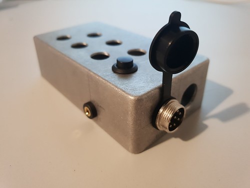
On the back, another 7mm hole was drilled for the 3.5mm jack that will be used to connect a foot-pedal for handsfree PTT operation.
Once all holes are drilled and all components are test fitted, you can start sanding the box and give it some layers of spray paint.
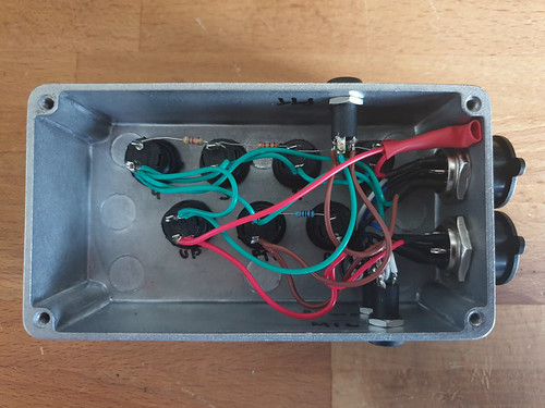
Put everything together
First, make sure you solder long ends of wire to the GX16 connectors. It would be a real challenge to solder them when they are already mounted in the enclosure.
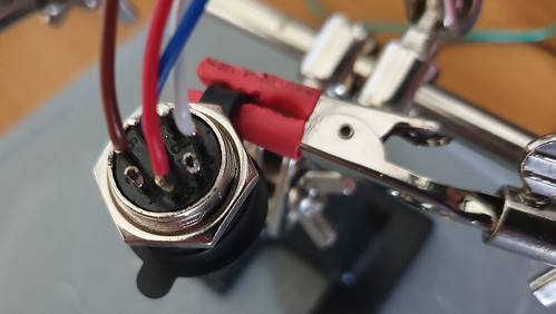
I opened the original Icom MH-219 to know what colour code they use and tried to use the same as much as possible.
Pin 1: Mic input = white
Pin 2: 8V = not used for this project
Pin 3: Frequency up and down = red
Pin 4: Squelch = not used for this project
Pin 5: PTT = brown
Pin 6: PTT Ground = green
Pin 7: Mic Ground = Black
Pin 8: AF output = Blue
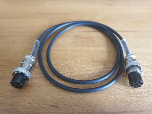
Now fix a connection cable with two female GX16-8 connectors, using an SP/2 extension cable and some clear tubing as stress relief. The colour scheme of this cable is different from that of Icom, but as long as you connect each wire to the same pin on the opposite side of the cable, you’re good to go.
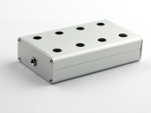
The finished product
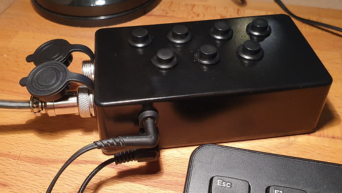
In this picture, the original mic and the foot pedal are not connected. I’m using an in-ear Sennheiser and a 1€ condenser boom mic from AliExpress. Maybe not the “best” solution, but for the moment good enough.
Everything works as it should and the magic smoke remained in the components where it belongs 😉
I will put this keyer to the test during the March 2019 CQ WPX contest. Hope to meet you on the band!
73 de ON5IA