Click on the images to go directly to the sections of the different external keypad designs.
Design A – V2.00
Design B – V1.00

Design C – V1.00
Design D – V1.00

What is it, and why would you need it?
A (voice, CW, RTTY) keyer is a tool to record and play back messages. When you are calling CQ, you don’t have to endlessly speak or send morse, the keyer can do that for you.
Many Icom radio’s have a built in voice keyer with 8 memory slots. However, you can only activate these via the touchscreen when you are in the keyer menu (obviously).
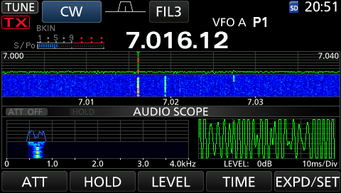
This keyer menu takes up 50% of the display, and prevents you from viewing other interesting screens, such as the extended waterfall or the audioscope.
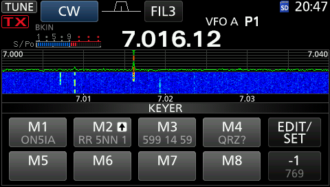
With the external keypad, you can address 4 or 8 memory channels (depending on the type of transceiver) without having the keyer menu on display. An additional advantage of an external keypad is that you can install it in a spot that is best accessible to you. In case of a contest e.g.: just next to your PC keyboard.
What’s next?
I’m working on a Design D, that is compatible with both Icom and Kenwood transceivers.
Need help?
If you have any questions regarding the design, or how you can manufacture the PCB, feel free to let me know in the comments, or send me an email (can be found on QRZ.com).
Interested in having an external keypad for your Icom radio, but you are not in the possibility to make it yourself, for whatever reason: don’t hesitate to send me an email.
License

This work is licensed under a Creative Commons Attribution-NonCommercial-NoDerivatives 4.0 International License.
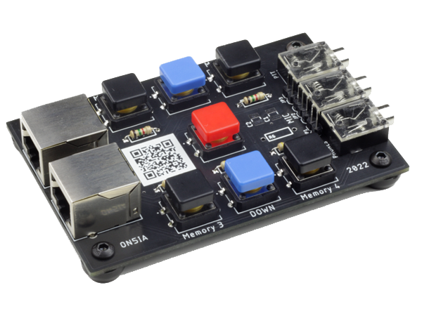
Design A – V2.00
Compatible with Icom IC-7300, IC-7610, IC-9100, IC-9700
Not sure if compatible with IC-7600 as the manual indicates to use pin 7 (mic ground) instead of pin 6 (PTT ground)

Parts list
- 3 x Stereo Sockets PJ-324
- 7 x Omron B3F-4055 with cap
- 2 x RJ45 / 8P8C connector (18mm)
- Resistors (although you need to buy them per 200)
- 1 x 470 Ohm resistor
- 2 x 1.5K Ohm resistor
- 1 x 2.2K Ohm resistor
- 1 x 4.7K Ohm resistor
- 1 x GX16 – 8 pin -Male and Female
- 1 m of 28AWG 8 Core signal wire
- 4 x M3 6mm bolts
- 4 x M3 Hex nuts
- 4 x 11 mm x 6 mm rubber feet
- 2 x 2 pin and 1 x 3 pin of a breakable header
Downloads
How to connect?
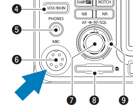
The external keypad Design A needs to be connected via the microphone connector. Indicated on the picture above by the blue arrow and the number 6. Check the blogpost of the Icom External Keypad Connector Cable for in structions how to build this cable.
Optional Capacitors and Resistor
C1, C2 and R6 are optional components. Whether you need them or not depends from the type of microphone you want to connect to your Icom radio through the 3.5mm jack. C1 and C2 for example is needed when you want to connect a dynamic microphone. It’s not needed when you use an electret microphone. C1 should be a non polarised tantalum capacitor, but as I found out these are harder to find than polarised tantalum capacitors, I foresaw to place 2 polarised tantalum capacitors in series. When you want to use polarised capacitors, you need only half the value and need to place them + to + or – to -.
R6 is needed when you need “phantom power” between 0v and 8v. (https://heilsound.com/heil-amateur-radio/support/dsp-settings/all-things-icom/)
You don’t need to install these components if you already can use your microphone directly with your rig.
Connector Cable
For information about the connector cable, check out this blogpost: Icom External Keypad Connector Cable. Please not that I assigned pin 1 of the RJ45 to pin 1 of the GX16 8-pin connector. This is not the same order as Icom is using for the IC-7100. IC-7100 assecories are not compatible with this version of the keypad.
What are the jumpers for?
The jumpers allow a variety of microphones to be connected through the external keypad.
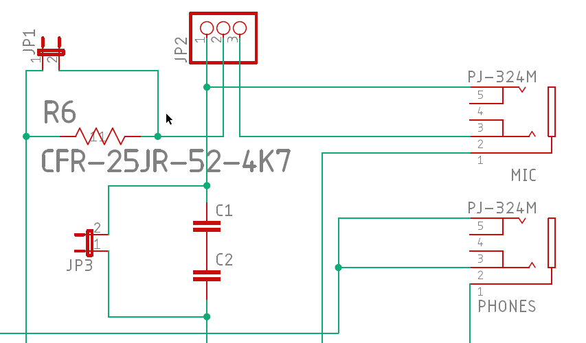
JP1 is located on the line that carries 8v (pin 2 of the GX16 connector) and is in parallel with R6. When you place jp1 you provide the tip of your microphone plug with 8V. If you need less than 8V leave out JP1 and place a resistor with a suitable value to get the voltage you need for your microphone.
JP2 can be placed in two positions. When using a microphone with a mono plug, set the jumper over pin 1 and 2. When using a microphone with a tip-ring-shield 3.5mm jack, and you need phantom power on the ring, set the jumper over pin 2 and 3.
JP3 needs to be placed if you use an electret condenser microphone. If you use a dynamic microphone, do not set JP3 but install the C1 and C2 (tantalum capacitors) of the right value needed for your microphone.
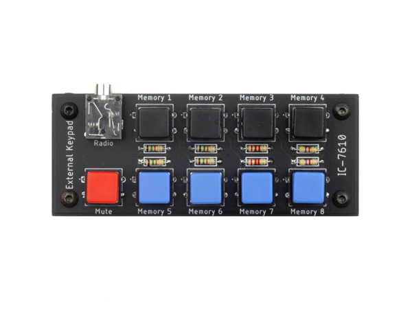
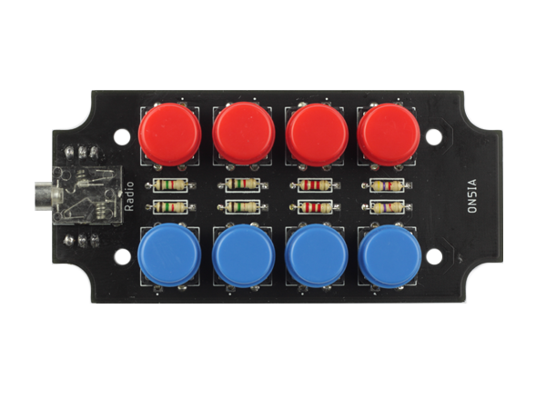
Design B
Compatible with IC-7610
Parts list
- 1 x Stereo Sockets PJ-324
- 9 x Omron B3F-4055 with cap
- Resistors (although you need to buy them per 200)
- 4 x 1.5K Ohm resistor
- 2 x 2.2K Ohm resistor
- 2 x 4.7K Ohm resistor
- 1 x 3.5 mm aux cable
- 4 x M3 6mm bolts
- 4 x M3 Hex nuts
- 4 x 13 mm x 7 mm rubber feet
Downloads
How to connect?
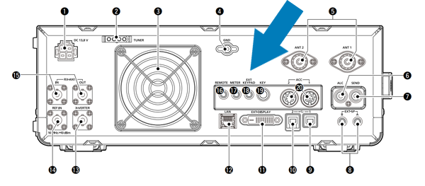
The external keypad Design B connects to your ic-7610 via the ext keypad jack on the back of the transceiver. On the picture above, the jack is indicated by a blue arrow and the number 18. You can use a regular 3.5mm aux cable as a connector cable.
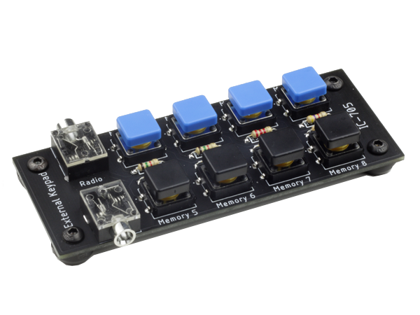
Design C
Compatible with IC-705
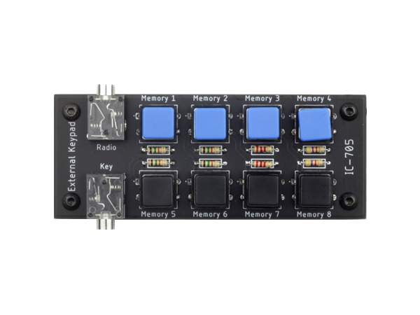
Parts list
- 2 x Stereo Sockets PJ-324
- 8 x Omron B3F-4055 with cap
- Resistors (although you need to buy them per 200)
- 4 x 1.5K Ohm resistor
- 2 x 2.2K Ohm resistor
- 2 x 4.7K Ohm resistor
- 1 x GX16 – 8 pin -Male and Female
- 1 x 3.5 mm aux cable
- 4 x M3 6mm bolts
- 4 x M3 Hex nuts
- 4 x 13 mm x 7 mm rubber feet
Downloads
How to connect?

The external keypad Design C connects to your IC-705 via the key jack on the right sidepanel of the transceiver. On the picture above, the jack is indicated by a blue arrow and the number 4. You can use a regular 3.5mm aux cable as a connector cable. When the external keypad is plugged into the key jack, you can connect your straight key, keyer or paddle through the key connector on the external keypad.
Design D
Compatible with Icom IC-7610, IC-705 and Kenwood TS 990
Parts list
- 1 x Stereo Sockets PJ-324
- 8 x Omron B3F-4055 with cap
- Resistors (although you need to buy them per 200)
- 4 x 1.5K Ohm resistor
- 2 x 2.2K Ohm resistor
- 2 x 4.7K Ohm resistor
- 1 x 3.5 mm aux cable
- 4 x M3 10mm tapping screws
- 4 x M3 3mm spacers
- 1 x Hammond 1591XXASBK enclosure
Downloads
How to connect?
The external keypad Design D connects to your IC-7610 or Kenwood TS-990(s) via the ext keypad jack on the back of the transceiver or to your IC-705 via the key jack on the right sidepanel of the transceiver.
You can use a regular 3.5mm aux cable as a connector cable.
On the back of the PCB, there are jumpers that needs to be set depending on the brand of radio you are using the keypad with. To use it with a kenwood, JP1 and JP2 need to be placed over pin 1 and 2. For Icom radio’s JP1 and JP2 need to be place over pin 2 and 3.
Hello, in version 1.21, Resistor R6 and capacitor C1 What values do they have to have?
What is the purpose of these two components?
EA1AHA
Hello Juan Carlos,
The C1 capacitor blocks the voltage to the mic element. This can be needed when you want to connect a dynamic microphone to your Icom. You can find more info about this on the website of Heil Sound. (https://heilsound.com/heil-amateur-radio/support/dsp-settings/all-things-icom/)
The R6 resistor is foreseen in case you want to connect an electret microphone that needs some voltage between 0V and 8V. The value of the resistor needs to be chosen based on the voltage you need.
Both C1 and R6 are optional components that are specific to the microphone you want to connect via the 3.5mm jack on the keyboard. They both can be bypassed by setting jumpers (or not).
If you only want to connect the keyboard between your Icom mic (or any mic that you already can connect directly to your rig) you dont need these two components.
And you also don’t need them if you use a condenser mic like this for example: https://s.click.aliexpress.com/e/_AMoQWi
73 de ON5IA
Hi I do like the way you are making the external keyboards could I have a copy of the gerber file for the version 1.21 Thank you
Hello Don, sure! I’ll send you an email with the latest geber files of v2.02.
Meanwhile, I was able to assemble and test this latest version. It will be released on the website this weekend. You get the premiere!
73 de ON5IA
Hallo OM ON5IA…
Meine Frage ist , ist ein 3D Gehäuse oder ein anderes Gehäuse für die – (IC-7300 Keyboard V2.0) – Leiterplatte erhältlich?
Gruß Wolfgang DM2OV
Hallo Wolfgang,
Noch nicht, aber ich arbeite an einer Version, die in ein Metallgehäuse passt und leicht nachgebaut werden kann. Es wird aber noch einige Zeit dauern, bis ich damit fertig bin, denn es stehen noch andere Projekte auf der To-Do-Liste 😉
Vielen Dank im Voraus für Ihr Interesse!